


Results 1 to 25 of 25
Thread: How to read compressor maps
-
07-21-2011, 07:17 PM #1
 Supporting Vendor


- Join Date
- Jul 2010
- Location
- Encino,CA
- Posts
- 9,962
- Rep Points
- 8,426.4
- Mentioned
- 311 Post(s)
- Rep Power
- 85
2 out of 2 members liked this post. Reputation

How to read compressor maps
Copied off a site lol...
This guide isn't meant to be an in-depth look at turbo sizing, but rather to give the reader a working knowledge of how to read maps. In other words, to decipher what all those swirling lines mean when choosing a turbo compressor.
Terminology
Compressor - This is the "cold" side of the turbo that sucks in intake air and compresses it for the engine to later combust with fuel.
Turbine - This is the "hot" side of the turbo. Hot exhaust gasses pass through it, expanding and cooling. This expansion spins a turbine that the compressor wheel via a shaft. Unfortunately turbo manufacturers don't make turbine maps available to the general public.
Absolute Pressure - This is pressure referenced from a pure vacuum. Most calculations done involving compressors use absolute pressure. Note - 1 atmosphere = ~14.7 psia (Absolute pressure in pounds per square inch) = 0 psig (gage pressure in pounds per square inch). Your boost gauge reads in psig, referenced to local atmospheric pressure.
ONTO THE MAPS
Surge - This is lowest amount of airflow a compressor can supply at a given pressure ratio(getting to that). Any pressure above this at this airflow, the compressor will "gulp" air. This is not good for your turbo, or your power output. Fortunately you have to saddle a pretty huge compressor with a small turbine to really worry about this effect.
Here is a compressor map with the surge line highlighted in red.
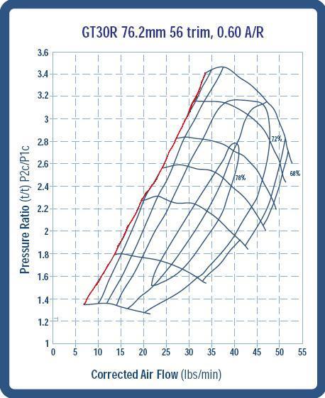
On the X-axis(horizontal) you'll notice the mass airflow of the compressor in lbs/min. On the Y-axis there is the Pressure Ratio. Pressure ratio is defined as follows:
Atmospheric Pressure + Boost Pressure = Pressure Ratio
Atmospheric Pressure
So the astute reader will notice a pressure ratio of 1.0 is the exact same as atmospheric. A pressure ratio of 2.0 is equivalent to 1 atmosphere or ~14.7 psig in your intake manifold. Without concrete data proving otherwise, it is always the best course of action to assume the pressure is ambient at the compressor inlet and make note of the pressure drops of the system will in the end cause less to be produced than the mass flowrate of the turbo would suggest.
The oval shaped rings on the compressor map are efficiency islands. These are regions where the compressor has approximately the same efficiency at compressing the air. Of course, the higher the efficiency the better since the compressor will be introducing less unneeded heat into the charge air. Note that as you go away from the maximum efficiency island, you always go down in efficiency. By the time you're off the map you're usually in the <60% range, which is not a good thing.
The lines that slope from the surge line to the right and down across the efficiency islands are constant speed lines. This would be really useful if you could match up the speed of the compressor to the speed of the turbine and find out its efficiency and mass flowrate for that shaft speed, but since we don't have turbine maps we're kind of at a disadvantage there for picking the ultimate turbo match. The maps used here out of Garrett's publicly available catalog aren't too detailed. Some maps will have much more data like putting RPM values on the speed lines, more efficiency islands etc.
I won't go into the hard equation to calculate the mass airflow of the engine, as it really doesn't gain anybody any further insight into the turbo selection process. The only important things to understand that the big factors in how much mass airflow an engine is consuming are:
- Engine Displacement
- Volumetric Efficiency(how well the engine breathes)
- Pressure at the inlet valves(BOOST!)
- RPM
By altering these things(more displacement, cams to increase VE, more boost, more RPMs) you can make the engine combust more air and make more power. I'll be attaching a spreadsheet that makes calculating the airflow of an engine an easy matter. It does over simplify things since it doesn't vary VE by RPM and whatnot, but it is a reasonably close approximation. I use a VE of 90% in most my calculations. It is pretty close to what a modern 4 valve engine gets in high RPMs, and tends to be conservative on less modified engines.
So go ahead and download the spreadsheet and we can look at a compressor map.
Here I'll look at a GT30R turbo on an S52B32 engine with a VE of 90%, displacement of 3.2L and maximum RPM of 7000. For the first go, we'll see what happens at a modest boost level of ~8.7 psi(pressure ratio of 1.6).
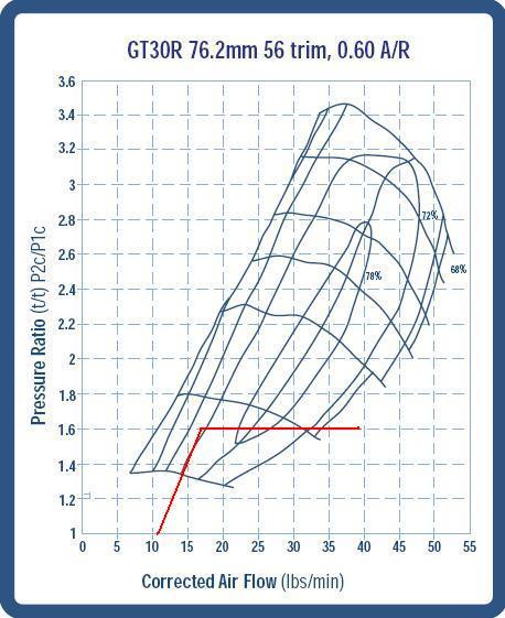
How I evaluate compressor maps is to note the airflow at 2000 RPM. Find that on the X-axis and draw a straight line from that point at a PR of 1 to the airflow at 3000 RPM at your desired PR(1.6 in this case). This gives you an idea of how a typical turbo will look when spooling up, and let you know if it's at a risk of surging. From there, the line should stay at that PR all the way to the airflow at redline ~39 lb/min here.
As you can see, surge is not a problem here, but this turbo sure does look a bit too small for this sized engine! It goes off the map just before redline, so that means it is very inefficient at higher revs.
Let's see what happens when we up the boost to ~17.4 psi(PR of 2.2).
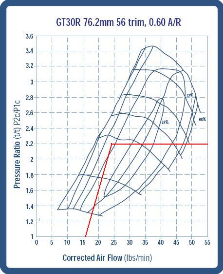
No risk of surge due to this being a large engine for the turbo, but boy does it ever get REALLY inefficient at higher revs. Past 6000 RPM it is again off the map.
Let's go to a slightly larger turbo, a GT35R, to see the difference. Same boost of 17.4 psi(PR of 2.2).
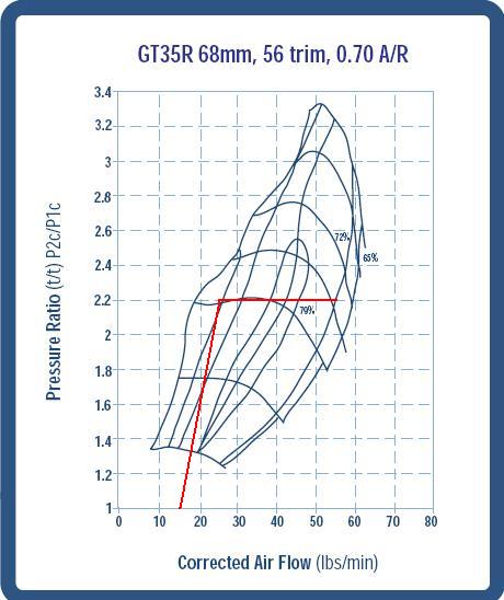
Now that is more like it! Notice how the engine spends a good amount of time in the really efficient islands, and the turbo is still at 72% efficiency all the way to redline. I'd think this turbo would be putting out in the 450-500rwhp range at this boost on this engine, and that's probably being a bit conservative. If the VE of the engine was even higher(which it can be), this turbo could still put out even more power. The compressor map also suggests it has a bit more headroom on this particular engine.
I hope that was helpful to everybody, and gives people a start in the right direction on reading compressor maps themselves. If you want to modify the Excel airflow chart I attached, just extend the RPM row and copy the formula in the airflow cells for CFM and lb/min over below the RPM and it should fill in correctly. You can change the displacement, VE and pressure ratio in the parameters section to get an idea of how these change things.
Enjoy boost junkies!Burger Motorsports
Home of the Worlds fastest N20s, N54s, N55s, S55s, N63s, and S63s!
It is the sole responsibility of the purchaser and installer of any BMS part to employ the correct installation techniques required to ensure the proper operation of BMS parts, and BMS disclaims any and all liability for any part failure due to improper installation or use. It is the sole responsibility of the customer to verify that the use of their vehicle and items purchased comply with federal, state and local regulations. BMS claims no legal federal, state or local certification concerning pollution controlled motor vehicles or mandated emissions requirements. BMS products labeled for use only in competition racing vehicles may only be used on competition racing vehicles operated exclusively on a closed course in conjunction with a sanctioned racing event, in accordance with all federal and state laws, and may never be operated on public roads/highways. Please click here for more information on legal requirements related to use of BMS parts.
-
07-22-2011, 12:20 AM #2
Member
- Join Date
- May 2010
- Location
- CT
- Posts
- 1,729
- Rep Points
- 826.2
- Mentioned
- 0 Post(s)
- Rep Power
- 9
Reputation
I need to re-read this but I've always wondered how to read these
 JB4LIFE
-
07-22-2011, 01:42 AM #3
Supporting Vendor
- Join Date
- Jul 2010
- Location
- Encino,CA
- Posts
- 9,962
- Rep Points
- 8,426.4
- Mentioned
- 311 Post(s)
- Rep Power
- 85
Reputation
I've read this numerous of times. You have to understand the formula bs, but otherwise I kinda get it.. but meh
Burger Motorsports
Home of the Worlds fastest N20s, N54s, N55s, S55s, N63s, and S63s!
It is the sole responsibility of the purchaser and installer of any BMS part to employ the correct installation techniques required to ensure the proper operation of BMS parts, and BMS disclaims any and all liability for any part failure due to improper installation or use. It is the sole responsibility of the customer to verify that the use of their vehicle and items purchased comply with federal, state and local regulations. BMS claims no legal federal, state or local certification concerning pollution controlled motor vehicles or mandated emissions requirements. BMS products labeled for use only in competition racing vehicles may only be used on competition racing vehicles operated exclusively on a closed course in conjunction with a sanctioned racing event, in accordance with all federal and state laws, and may never be operated on public roads/highways. Please click here for more information on legal requirements related to use of BMS parts.
-
07-22-2011, 02:44 AM #4
Member
- Join Date
- May 2010
- Location
- CT
- Posts
- 1,729
- Rep Points
- 826.2
- Mentioned
- 0 Post(s)
- Rep Power
- 9
Reputation
Just slap a big turbo on and let it rip is what I've always said Originally Posted by fastgti69
 JB4LIFE
-
07-22-2011, 11:57 AM #5
Supporting Vendor
- Join Date
- Jul 2010
- Location
- Encino,CA
- Posts
- 9,962
- Rep Points
- 8,426.4
- Mentioned
- 311 Post(s)
- Rep Power
- 85
Reputation
Pretty much, see what hp rating you want to be in between and choose that turbo lol Originally Posted by mazdaspeed6
Burger Motorsports
Home of the Worlds fastest N20s, N54s, N55s, S55s, N63s, and S63s!
It is the sole responsibility of the purchaser and installer of any BMS part to employ the correct installation techniques required to ensure the proper operation of BMS parts, and BMS disclaims any and all liability for any part failure due to improper installation or use. It is the sole responsibility of the customer to verify that the use of their vehicle and items purchased comply with federal, state and local regulations. BMS claims no legal federal, state or local certification concerning pollution controlled motor vehicles or mandated emissions requirements. BMS products labeled for use only in competition racing vehicles may only be used on competition racing vehicles operated exclusively on a closed course in conjunction with a sanctioned racing event, in accordance with all federal and state laws, and may never be operated on public roads/highways. Please click here for more information on legal requirements related to use of BMS parts.
-
07-30-2011, 11:44 PM #6
Regular User

- Join Date
- Jan 2010
- Location
- SoCal
- Posts
- 148,074
- Rep Points
- 47,180.6
- Mentioned
- 2523 Post(s)
- Rep Power
- 472
Reputation
Thanks for this, less confused now
-
12-20-2012, 07:37 AM #7
Regular User
- Join Date
- Jan 2010
- Location
- SoCal
- Posts
- 148,074
- Rep Points
- 47,180.6
- Mentioned
- 2523 Post(s)
- Rep Power
- 472
Reputation
Moved this to Advanced Tech, completely forgot about it.
-
12-20-2012, 07:55 AM #8
Member
- Join Date
- May 2010
- Location
- PEI, Canada
- Posts
- 1,121
- Rep Points
- 1,665.0
- Mentioned
- 30 Post(s)
- Rep Power
- 17
Reputation
You know the problem with picking an efficiency out of the sky? There's nothing behind it.
I took known engine parameters, from an engine I had spent a lot of time on the dyno with, and arrived at efficiency well above 90% in an engine simulation program that's pretty well respected. (Pipemax)
While the example above is a good start, there are a lot of other variables that need to be added to the equation, like varying engine frictional losses, and pumping losses across RPM. An engine doesn't have 1 static pumping efficiency.
Ug...I may be painting myself into a corner here where Sticky asks me to write an article on this....Rep Points > Posts since 2010
-
12-20-2012, 07:56 AM #9
Regular User
- Join Date
- Jan 2010
- Location
- SoCal
- Posts
- 148,074
- Rep Points
- 47,180.6
- Mentioned
- 2523 Post(s)
- Rep Power
- 472
Reputation
Well, it didn't help that you suggested it. Originally Posted by PEI330Ci
Fact is we could use a good article on this topic.
-
12-21-2012, 02:21 AM #10
Member
- Join Date
- May 2010
- Location
- PEI, Canada
- Posts
- 1,121
- Rep Points
- 1,665.0
- Mentioned
- 30 Post(s)
- Rep Power
- 17
Reputation
That's what I thought I was going to read when I opened this thread. I need to learn too!!! Originally Posted by Sticky
Rep Points > Posts since 2010
-
09-27-2014, 12:23 AM #11
Member
- Join Date
- Sep 2014
- Posts
- 38
- Rep Points
- 101.3
- Mentioned
- 2 Post(s)
- Rep Power
- 2
3 out of 3 members liked this post. Reputation
The descriptions in the copied article aren't too bad, but I had a couple of thoughts though while reading it.
The definition of PR: I think it may be safer to simply define it as 'compressor diffuser exit pressure'/'compressor impellor inlet pressure'. Losses in the air intake and the air temperature in the engine bay will make the impellor 'see' a different pressure than strictly ambient (I'm assuming here that ambient pressure refers to the air Total Pressure outside of the vehicle).
When discussing either flow or compressor/turbine speed, these terms should always be understood as 'corrected' flow ror speed. Corrected flow is defined as (mass-flow-rate)*sqrt(Total-Temperature/Total-Temperature[standard-day])/(Total-ryPressure/Total-Pressure[standard-day]). Corrected % speed is defined as Rpm/sqrt(Total-Temperature/Total-Temperature[standard-day]).
In the graphs of the compressor maps, red lines show an initial diagonal spool up, followed by a flat line. I'm not sure if the flat line is supposed to represent theso called 'working line' of the turbomachine in these plots. Usually the WL is also somewhat diagonal, and is dependent on the corrected rpm and corrected compressor-exit flow conditions.
You ususlly want to run a compressor between 90% to 100% corrected speed (with some surge 'margin') as this gives you the best combination of PR and efficiency.
-
09-27-2014, 01:20 PM #12
Regular User
- Join Date
- Jan 2010
- Location
- SoCal
- Posts
- 148,074
- Rep Points
- 47,180.6
- Mentioned
- 2523 Post(s)
- Rep Power
- 472
Reputation
Seriously, are you female? Originally Posted by skyegirl
-
09-27-2014, 01:50 PM #13
Member
- Join Date
- Dec 2013
- Location
- Fort Mac, AB
- Posts
- 1,405
- Rep Points
- 789.0
- Mentioned
- 23 Post(s)
- Rep Power
- 8
Reputation
If she is she definitely works in a technical field. Her conclusions are sound. Originally Posted by Sticky
07 335XI(A008006) 6AT ~105K miles JB4 G5 ISO VSRF DP's
09 135I(VK80379) 6MT. Race Project car.
1) Install Modified Motiv 600 Kit[HTA3076R w/ tial .82] 2) Moton 4 suspension. 3) Build high flow intake manifold with multi-port fuel and relocate OFH 4) Build full cage possible rear diff upgrade 5) Complete staged twin setup with HTA4205R [w/Tial 1.16] 6) Complete dry sump system 7) Sequential maybe
-
09-27-2014, 04:37 PM #14
Member
- Join Date
- Sep 2014
- Posts
- 38
- Rep Points
- 101.3
- Mentioned
- 2 Post(s)
- Rep Power
- 2
4 out of 4 members liked this post. Reputation
He, hee
Yes, I'm female. Ingeniator was right, I work in a technical field - I have a PhD in turbomachinery aerodynamics, and work in aircraft engine design. There are alot of us gals in this business.
I like driving, and recently 'discovered' turbomachinery in forced-induction car engines, so now I'm hooked. The 'skye' in my username refers to a roadtrip I took through the UK where I went through all the national parks, via every famous driving road I could find (e.g. snake pass, ribblehead run, buttertubs pass). I ended up in the Scottish Highlands, on the A82 road. I went through Glencoe, the Isle of Skye, and finally through Loch Ness. It was epic. TMI?
-
09-27-2014, 04:41 PM #15
Member
- Join Date
- Dec 2013
- Location
- Fort Mac, AB
- Posts
- 1,405
- Rep Points
- 789.0
- Mentioned
- 23 Post(s)
- Rep Power
- 8
Reputation
Siemens? Originally Posted by skyegirl
07 335XI(A008006) 6AT ~105K miles JB4 G5 ISO VSRF DP's
09 135I(VK80379) 6MT. Race Project car.
1) Install Modified Motiv 600 Kit[HTA3076R w/ tial .82] 2) Moton 4 suspension. 3) Build high flow intake manifold with multi-port fuel and relocate OFH 4) Build full cage possible rear diff upgrade 5) Complete staged twin setup with HTA4205R [w/Tial 1.16] 6) Complete dry sump system 7) Sequential maybe
-
09-27-2014, 04:46 PM #16
Supporting Vendor
- Join Date
- Jul 2010
- Location
- Encino,CA
- Posts
- 9,962
- Rep Points
- 8,426.4
- Mentioned
- 311 Post(s)
- Rep Power
- 85
Reputation
Where have you been all my life? A woman with a Phd in turbo-machinery and aerodynamics, am I dreaming? Originally Posted by skyegirl
Burger Motorsports
Home of the Worlds fastest N20s, N54s, N55s, S55s, N63s, and S63s!
It is the sole responsibility of the purchaser and installer of any BMS part to employ the correct installation techniques required to ensure the proper operation of BMS parts, and BMS disclaims any and all liability for any part failure due to improper installation or use. It is the sole responsibility of the customer to verify that the use of their vehicle and items purchased comply with federal, state and local regulations. BMS claims no legal federal, state or local certification concerning pollution controlled motor vehicles or mandated emissions requirements. BMS products labeled for use only in competition racing vehicles may only be used on competition racing vehicles operated exclusively on a closed course in conjunction with a sanctioned racing event, in accordance with all federal and state laws, and may never be operated on public roads/highways. Please click here for more information on legal requirements related to use of BMS parts.
-
09-27-2014, 05:02 PM #17
Regular User
- Join Date
- Jan 2010
- Location
- SoCal
- Posts
- 148,074
- Rep Points
- 47,180.6
- Mentioned
- 2523 Post(s)
- Rep Power
- 472
2 out of 2 members liked this post. Reputation
Oh no, please go on. Originally Posted by skyegirl
I think further details on your age and relationship status would be quite useful as well.
-
09-28-2014, 11:34 PM #18
Member
- Join Date
- Sep 2014
- Posts
- 38
- Rep Points
- 101.3
- Mentioned
- 2 Post(s)
- Rep Power
- 2
1 out of 1 members liked this post. Reputation
I need to make a correction (pardon the pun) to the definition of corrected speed in post #11 above. I stated 'corrected % speed' when I should have said 'corrected speed' for the equation as written.
Incidentally, does anyone know how the design-point corrected speed is defined for turbochargers? I think the design-point temperature may simply be sea-level standard day, but it would be good to have that confirmed. It would also be good to know the convention for setting the design point for turbocharger applications. Is it relative to a compressor 'redline' speed, say approx. 10% below this speed, with 15% surge margin?
-
09-28-2014, 11:37 PM #19
Regular User
- Join Date
- Jan 2010
- Location
- SoCal
- Posts
- 148,074
- Rep Points
- 47,180.6
- Mentioned
- 2523 Post(s)
- Rep Power
- 472
Reputation
I may be in love.
-
09-29-2014, 05:06 PM #20
Motoza tune
- Join Date
- Jan 2013
- Posts
- 840
- Rep Points
- 1,065.0
- Mentioned
- 6 Post(s)
- Rep Power
- 11
Reputation
Will you marry me? Originally Posted by skyegirl
FIRST!

-
09-29-2014, 05:07 PM #21
Motoza tune
- Join Date
- Jan 2013
- Posts
- 840
- Rep Points
- 1,065.0
- Mentioned
- 6 Post(s)
- Rep Power
- 11
Reputation
She's like the female version of you. Originally Posted by Sticky
-
09-29-2014, 05:24 PM #22
Member
- Join Date
- Dec 2013
- Location
- Fort Mac, AB
- Posts
- 1,405
- Rep Points
- 789.0
- Mentioned
- 23 Post(s)
- Rep Power
- 8
Reputation
Your starting to exceed my limited experience with turbo machinery. I thought test conditions are usually defined. But that is on the ones we get for our axial compressors at work. In this case they may be corrected for sea level and 15.5C but I have no evidence of this. Originally Posted by skyegirl
Here are some references. I've used to select base turbo sizes for my build.
Auto selectors.
http://www.turbos.bwauto.com/aftermarket/matchbot.aspx
http://www.turbobygarrett.com/turbob...t/boostadviser
Advanced tech info by garret.
http://www.turbobygarrett.com/turbob...bo_tech_expert
EDIT: Found this that says they are corrected by SAE guidlines to 14.696psia and 60f
http://www.forcedinductions.com/helpadvanced.htm07 335XI(A008006) 6AT ~105K miles JB4 G5 ISO VSRF DP's
09 135I(VK80379) 6MT. Race Project car.
1) Install Modified Motiv 600 Kit[HTA3076R w/ tial .82] 2) Moton 4 suspension. 3) Build high flow intake manifold with multi-port fuel and relocate OFH 4) Build full cage possible rear diff upgrade 5) Complete staged twin setup with HTA4205R [w/Tial 1.16] 6) Complete dry sump system 7) Sequential maybe
-
09-30-2014, 11:03 AM #23
Regular User
- Join Date
- Jan 2010
- Location
- SoCal
- Posts
- 148,074
- Rep Points
- 47,180.6
- Mentioned
- 2523 Post(s)
- Rep Power
- 472
Reputation
Not quite and that's probably a good thing. Originally Posted by AlexQuattro
-
09-30-2014, 09:30 PM #24
Member
- Join Date
- Sep 2014
- Posts
- 38
- Rep Points
- 101.3
- Mentioned
- 2 Post(s)
- Rep Power
- 2
Reputation
Thanks for posting the Garrett turbo links. I liked the turbo expert pages - they helped answer some questions
I think the ommission of corrected speed is a concern though, for instance:
If an air intake delivers air at standard day ambient, 519.7 R, to a compressor that has a standard day 100% corrected speed of 5000 RPM, then the compressor will run at its 100% corrected speed. If though the air intake delivers air to the compressor at 590.7 R, then at a mechanical RPM of 5000, the corrected speed will be about 94% corrected speed, this might leave some useful power on the table depending on the compressor map.
I think it would be cool to have public domain access to a FI engine model where you could estimate a compressor working line. I assume tuning shops have a capability like this, no?
-
09-30-2014, 11:35 PM #25
Member
- Join Date
- Dec 2013
- Location
- Fort Mac, AB
- Posts
- 1,405
- Rep Points
- 789.0
- Mentioned
- 23 Post(s)
- Rep Power
- 8
Reputation
The auto selectors I linked to are close to that but not what your looking for I don't think they fully model. Your talking working line as in relation to surge control and limit lines? I only operate this stuff so most of my understanding on turbos is based on axial hydrogen compressors.
07 335XI(A008006) 6AT ~105K miles JB4 G5 ISO VSRF DP's
09 135I(VK80379) 6MT. Race Project car.
1) Install Modified Motiv 600 Kit[HTA3076R w/ tial .82] 2) Moton 4 suspension. 3) Build high flow intake manifold with multi-port fuel and relocate OFH 4) Build full cage possible rear diff upgrade 5) Complete staged twin setup with HTA4205R [w/Tial 1.16] 6) Complete dry sump system 7) Sequential maybe


 Quote
Quote


mikasalo5000,...
We welcome mikasalo5000